Public-source technical review and proposed protocol. No private robot design, newly executed simulation or physical validation result is reported.
Abstract
Contact simulation connects a legged robot's equations of motion to its ability to support weight, resist slip and change footholds. A plausible animation does not establish that the selected contact law, numerical solution and physical system agree. This review distinguishes rigid unilateral contact, compliant point contact and pressure-field contact, then proposes a reproducible evaluation protocol for legged-robot research. The protocol separates geometry conventions, equation residuals, contact-law consistency, discretization sensitivity and comparison with independent measurements. It uses publicly defined idealized cases before proposing robot-level experiments. The principal outcome is a reporting framework: every result should identify the model assumptions, reference quantity, numerical settings and uncertainty needed to interpret it. No solver ranking, speedup, robot capability or newly measured result is claimed. The proposed protocol remains to be implemented and evaluated on a public benchmark package.
Index Terms: Legged robots, contact mechanics, numerical verification, simulation validation, reproducibility.
I. Introduction
A foot-ground interaction influences balance even when the controller is unchanged. The researcher must decide what the model represents: ideally rigid contact, a deliberately compliant layer, or a distributed contact patch. These choices change the equations and the interpretation of separation, deformation and force.
Verification asks whether a computation solves its stated mathematical problem accurately. Validation asks whether the selected model adequately represents observations for an intended use. NASA's public verification-and-validation guidance makes this distinction in computational fluid dynamics; this review adopts the terminology, without treating its application-specific procedures as a robot certification scheme. [1]
This article addresses three questions. What must be disclosed before two contact simulations can be compared? Which small tests can expose an incorrect implementation or a misunderstood model? What additional evidence is needed before extending a result to a complete legged robot?
II. Public Literature and Model Scope
Carpentier, Le Lidec and Montaut formulate rigid and compliant contact within a common optimization framework. Their paper illustrates why conditioning, convergence criteria and the precise problem being solved matter when comparing contact algorithms. This review does not reproduce their experiments or inherit their performance findings. [2]
MuJoCo uses a soft-contact formulation. Its documentation distinguishes collision detection, active constraints and solver parameters; its contact distance and margin must be interpreted according to that formulation. Consequently, treating every geometrical overlap as an implementation defect would be inappropriate for a deliberately compliant model. [3]
Drake's hydroelastic approach represents an approximate contact surface and pressure distribution. Its official tutorial explicitly distinguishes this model from continuum finite-element deformation. A pressure patch can improve the representation of net contact force and moment without becoming a structural stress analysis of the contacting components. [4]
| Model family | Intended abstraction | Appropriate question |
|---|---|---|
| Rigid unilateral contact | Nonpenetration with compressive normal reaction | Are the declared admissibility conditions and discrete dynamics satisfied? |
| Compliant point contact | Force response associated with a parameterized compliant interface | Does the simulated response agree with the chosen compliance and damping law? |
| Pressure-field contact | Distributed approximate pressure over a contact patch | Are patch geometry, force and moment consistent with that model? |
This comparison identifies different evaluation targets. It is not a ranking of simulators. [2]–[4]
III. Mathematical Formulation
A. Robot Dynamics
Let q denote configuration, v generalized velocity, M the inertia matrix, b the gravity and velocity-dependent terms, τ the applied generalized force and J the contact Jacobian. With contact reaction λ, the usual constrained dynamics are
This notation follows the public formulation in [2]. A model using a floating base should state its configuration and velocity conventions; q and v need not have identical dimensions.
B. Rigid, Nonadhesive Normal Contact
Define as positive separation and as compressive normal reaction. At the position level, an ideal unilateral constraint is expressed as
Equation (2) states that separated surfaces do not transmit normal compression and an active reaction occurs at zero ideal gap. Dynamic time-stepping methods may enforce related velocity- or impulse-level conditions; their discrete equations must be reported instead of assuming literal position-level complementarity. For isotropic Coulomb friction, the tangential force lies within
The inequality alone does not specify sticking versus sliding; the selected friction law completes the model. These are standard idealizations, not material parameters or operating limits for a particular robot. [2]
C. Proposed Diagnostic Quantities
For an implementation under test, this article proposes reporting the equation-of-motion residual
For a rigid formulation, separate diagnostics should record penetration, tensile normal reaction and complementarity error. Report physical units and the normalizing scales; adding meters and newtons into an unexplained single score is not meaningful. For a compliant formulation, compare response against its actual constitutive rule rather than demanding Eq. (2). Equation (4) can be small even when the contact model is unsuitable for the intended physical system: solving an equation accurately does not determine whether it was the right equation to use.
IV. Proposed Evaluation Protocol
The following is an original evaluation proposal assembled from the distinctions above. No test in this section has been run for this manuscript.
A. Declare the Problem Before Executing It
Each case should specify units, geometry, initial configuration, body inertias, surface normals, material or contact parameters, friction, actuation and boundary conditions. The package should also record the simulator version, integrator, time step, solver settings and output precision. A readable configuration file and a reference script should describe the same case.
Before interpreting a force trace, check the sign convention directly: increasing the declared normal distance should mean separation. Before comparing moments, place all force and moment outputs in the same frame and about the same reference point.
B. Begin With Small, Public Cases
| Proposed case | Quantity to inspect | Main purpose |
|---|---|---|
| Free body without contact | Motion and momentum change | Check gravity, inertia and integration conventions |
| Quasistatic normal approach and separation | Gap, reaction and full loading history | Check the declared activation and release behavior |
| Tangential loading with stated friction | Slip onset and tangential reaction | Check sticking/sliding interpretation |
| Symmetric support with symmetric loading | Resultant force and moment | Check frame conversion and contact aggregation |
| Rocking block on a plane | Contact location and resultant moment | Examine contact-patch evolution and representation sensitivity |
Each expected behavior must be derived for the model actually selected. A quasistatic case needs a sufficiently slow load path or an explicit static solution; otherwise inertia can invalidate a static reference. A symmetric case is a diagnostic, not a reason to impose equal force sharing on asymmetric geometry.
C. Separate Numerical Sensitivity From Parameter Uncertainty
The proposed study varies time step and solver tolerance while holding the physical model fixed. Where geometry is discretized, it separately varies that discretization. It then varies uncertain physical quantities, such as friction or compliance, without presenting that variation as numerical error.
NASA's public grid-convergence discussion explains why successive refinement and an asymptotic-error model are needed to estimate discretization effects. It also cautions that a numerically converged result can retain physical-model error. Contact transitions require particular care: this manuscript does not assume that a smooth Richardson-extrapolation model applies across an impact or a change in active contact. [5]
D. Extend to Robot-Level Questions
Only after the smaller cases are understood should a researcher examine support transitions, perturbations, actuator saturation and state-estimation effects on a public robot model. The proposed comparison keeps the controller and task definition fixed where possible. If a change requires retuning, the retuned and fixed-controller comparisons should be reported separately.
Physical validation would require independently measured quantities with stated uncertainty: for example, a force history, foot displacement, slip event or contact location. Calibration data and held-out evaluation data should be distinguished. Agreement with one calibrated loading condition should not be generalized to every surface or maneuver.
V. Reporting Framework and Expected Outputs
There are no new numerical results to report. A future implementation should publish complete case definitions, analysis code and the successful and unsuccessful outcomes. Suggested plots are gap and normal reaction versus time; tangential reaction versus slip; net force and moment residuals; and the quantity of interest versus discretization. Plot captions should identify the model and units, not merely display the simulator's name.
Each comparison should state which settings changed, whether run failures were included, and what constituted an incomplete run. A favorable final frame should not replace a trajectory. A speed comparison should report both accuracy conditions and computing environment so that faster execution is not confused with a looser problem.
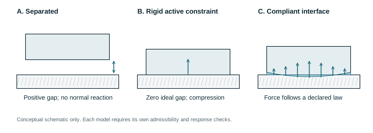
Figure 1 (proposed schematic). Distinguish separated rigid surfaces, an active rigid constraint and a compliant contact patch. The drawing is a conceptual illustration of model families; it represents no robot, measured deformation or simulation result.
VI. Limitations
This is a focused review, not a systematic survey or a new contact algorithm. The proposed test set has not been shown to detect every defect. Public simulator documentation can change, and different model families may answer different questions even when their images look alike. Neither software verification nor agreement with a limited physical experiment establishes whole-robot safety, durability or deployment readiness.
VII. Conclusion
Contact verification becomes interpretable when geometry, equations, numerical accuracy and physical observations are evaluated separately. The proposed protocol begins with small declared models and expands toward robot-level validation while preserving those distinctions. Its next research step is a public implementation and a documented evaluation, including failures and uncertainty.
Appendix. Printed Components and Model Validation
For contact-bearing printed components, a digital surface, an interchange file and a physical part provide different evidence. The 3MF specifications describe data interchange; a valid manufacturing package does not establish dimensional accuracy or mechanical fitness. This appendix proposes connecting measurements of printed geometry and loaded response to the contact model. It reports no fabrication or simulation experiment. [6]
NIST's AMB2018-03 polymer material-extrusion benchmark and its associated polycarbonate study provide a public example of controlled physical-property measurements for evaluating manufacturing models. Their properties and findings belong to the specified material, geometry and process. They must not be transferred to another polymer, printer, build orientation or process setting without supporting measurements. The benchmark is a methodological reference, not evidence for any QDOX component. [7], [8]
For a preselected feature relevant to contact or mounting, a proposed dimensional-deviation report is
Here, is an individual measurement and is the number of measurements. Report the feature definition, units, instrument, environment, individual deviations and variability. Repeated readings of one specimen and measurements across independently produced specimens characterize different variability and should remain distinguishable. Measurement uncertainty is not a manufacturing tolerance or an acceptance decision; its evaluation should follow an explicit measurement model. [9]
A prospective comparison should select a physical observable, such as displacement under a specified load, before simulation. State the constitutive assumptions, contact conditions, boundary conditions and intended use. For the same observable and conditions, the proposed normalized discrepancy is
The declared scale must have matching units. Equation (6) is a reporting convention, not a universal pass threshold. Numerical and measurement uncertainty must accompany the comparison. Agreement for one load, orientation or process setting does not validate a contact-bearing component outside that evaluated domain.
References
[1] NASA Glenn Research Center, “Overview of CFD Verification & Validation,” public technical guidance. Full text. Accessed 13 September 2026.
[2] J. Carpentier, Q. Le Lidec and L. Montaut, “From Compliant to Rigid Contact Simulation: a Unified and Efficient Approach,” arXiv:2405.17020, 2024. Public full text. DOI: 10.48550/arXiv.2405.17020.
[3] MuJoCo contributors, “Computation,” MuJoCo Documentation, version 3.7.0. Public documentation. Accessed 13 September 2026.
[4] Drake contributors, “Hydroelastic Contact: Basics,” official tutorial. Public tutorial. Accessed 13 September 2026.
[5] NASA Glenn Research Center, “Examining Spatial (Grid) Convergence,” public technical guidance. Full text. Accessed 13 September 2026.
[6] 3MF Consortium, “3MF Specifications,” official specification collection. Public specifications. Accessed 13 September 2026.
[7] National Institute of Standards and Technology, “AMB2018-03 Description: Materials Extrusion Polymer 3D Builds,” public benchmark description. Benchmark description.
[8] D. P. Cole et al., “AMB2018-03: Benchmark Physical Property Measurements for Material Extrusion Additive Manufacturing of Polycarbonate,” Integrating Materials and Manufacturing Innovation, 2020. NIST publication record. DOI: 10.1007/s40192-020-00188-y.
[9] Joint Committee for Guides in Metrology, Evaluation of Measurement Data—Guide to the Expression of Uncertainty in Measurement, JCGM 100:2008. Official collection, including supplements and amendments. DOI: 10.59161/JCGM100-2008E.
Data and Code Availability
This review creates no experimental dataset and claims no reproduced benchmark. Its sources are the public publications and documentation above. The proposed protocol is not an implemented software package. Any future experimental paper should link its own publicly available inputs, code and results.
Preparation Note
OpenAI Codex assisted with public-source review, drafting, equations and original vector diagrams. This document reports no newly executed hardware or robot experiment. Its structure borrows conventions from IEEE author guidance; no IEEE submission, acceptance, endorsement or peer review is represented.
Have a thought or an experience to share?
Write to us ↗